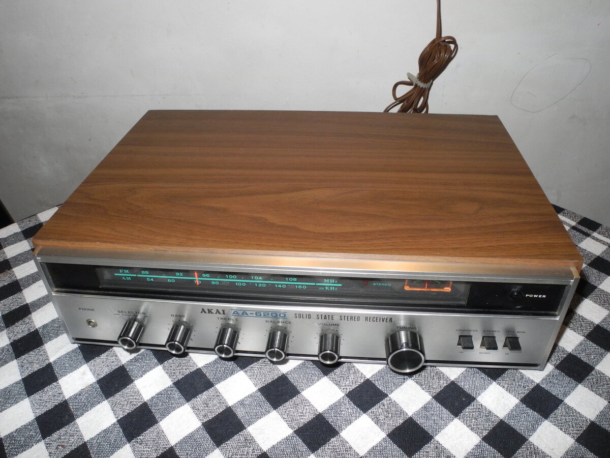
Akai AA-6200
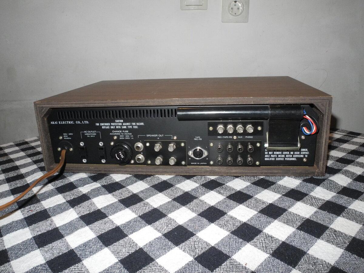
The Akai AA-6200 is a vintage solid-state stereo receiver from the early 1970s, designed during a time when Akai was gaining recognition for quality and durability in home audio equipment. Modest in power but rich in character, it offers a warm, musical sound that many vintage audio fans still appreciate today. The front panel features a classic brushed aluminum faceplate, a large tuning dial with an analog needle, and solid-feeling knobs for volume, tone, balance, loudness, and input selection. Inputs include phono, AUX, and tape, allowing easy connection of turntables, cassette decks, or other sources.

General Specifications
Maximum power (8Ω): 10W min*Frequency response (-3dB): 20Hz-50kHz
THD+N: 0.2%
Signal to noise ratio (Line): 70dB
Signal to noise ratio (Phono): 60dB
Input sensitivity (Line): 150mV
Input sensitivity (Phono): 3mV
Speaker load impedance: 8Ω*
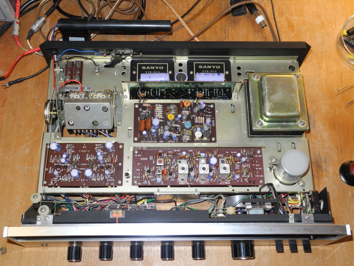
*Values taken from STK015 specification sheet
Dimensions (WHD): 445×133×340mm
Weight: 8.4kg
Produced: 1968
Measured Values
Maximum power (8Ω): 10WFrequency response (20Hz-20kHz): <4.0dB
Channel imbalance: <1.0dB
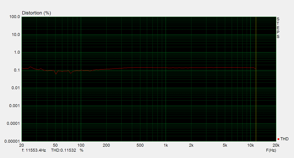
THD (1kHz, 1W): 0.14%
THD+N (1kHz, 1W): 0.18%
THD (1kHz, 20W): 0.28%
THD+N (1kHz, 20W): 0.28%
IMD (70Hz, 5kHz, 1W): 0.50%
Noise: -50.5dB
Amplification: 34.1
DC offset L: 0mV - by design
DC offset R: 0mV - by design
Maximum Power
Maximum power is measured using 8Ω resistors on both channels. A 1kHz sine wave input signal is applied and gradually increased until higher harmonics rise significantly. Typically, this is the point at which output clipping occurs.
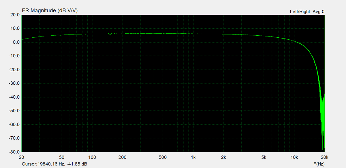
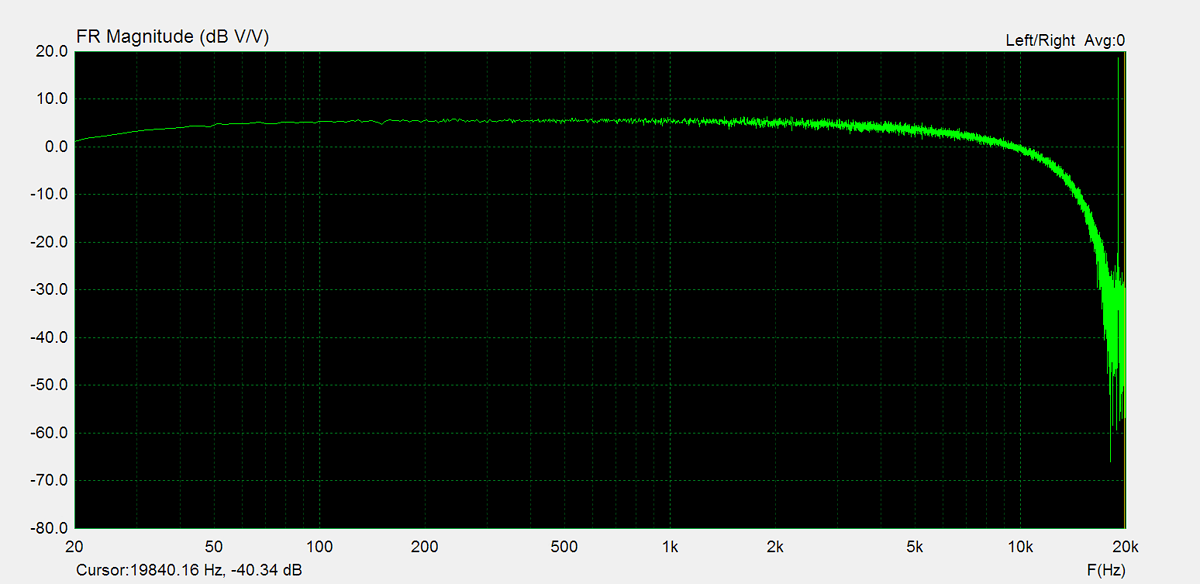
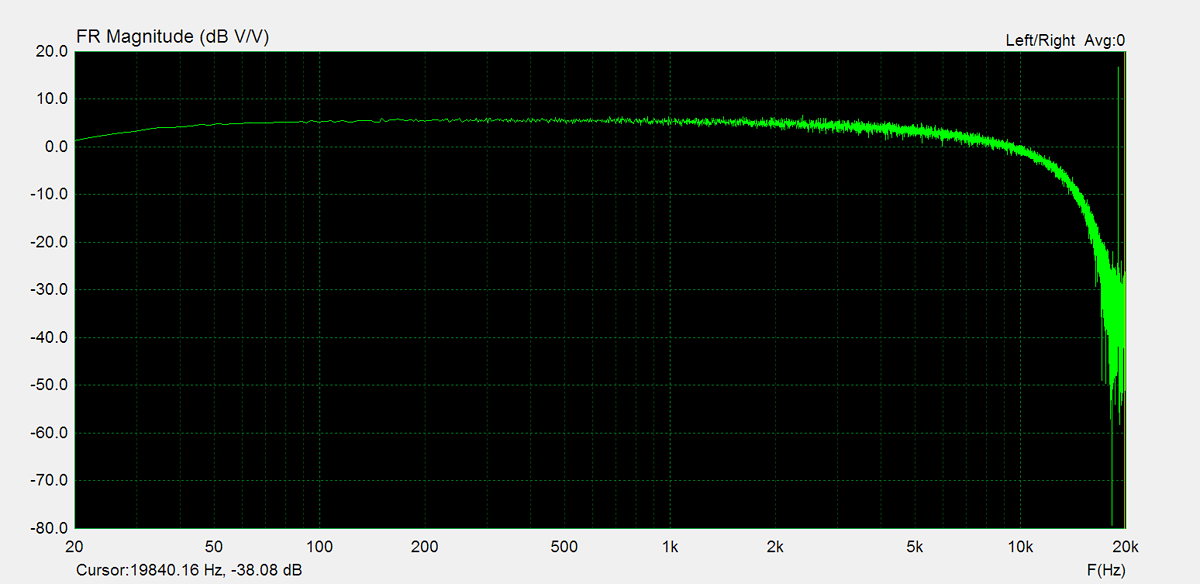
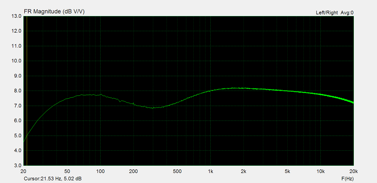
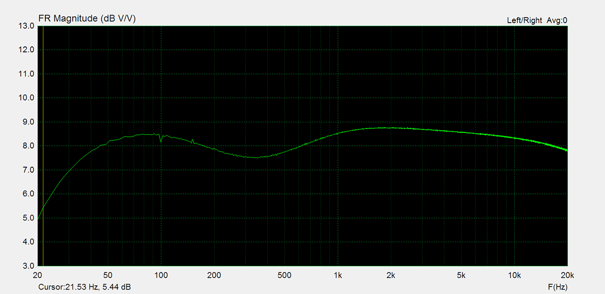
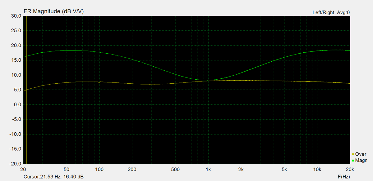
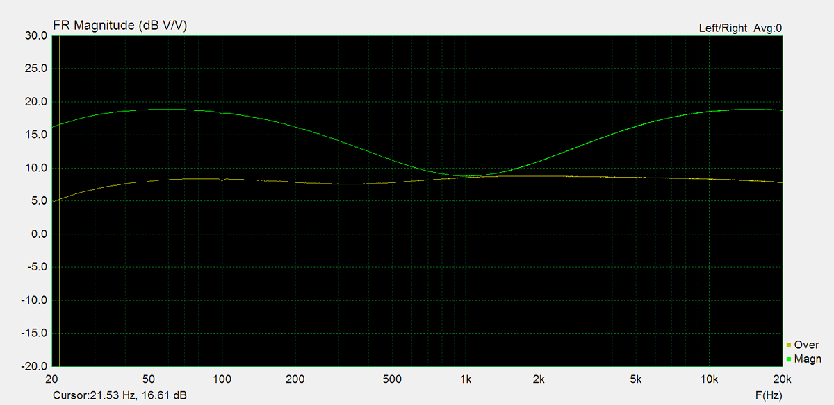
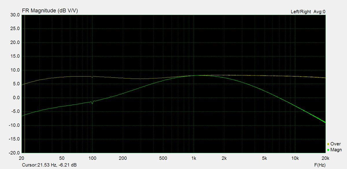
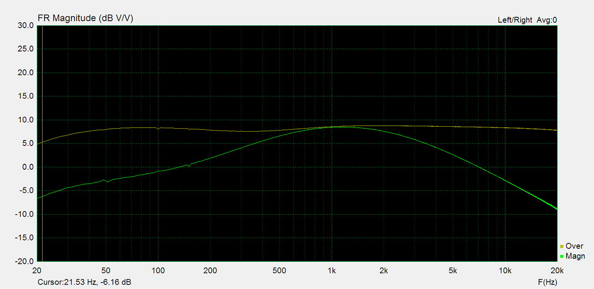
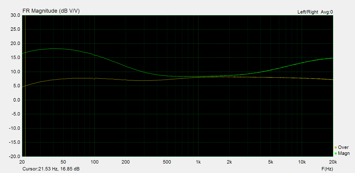
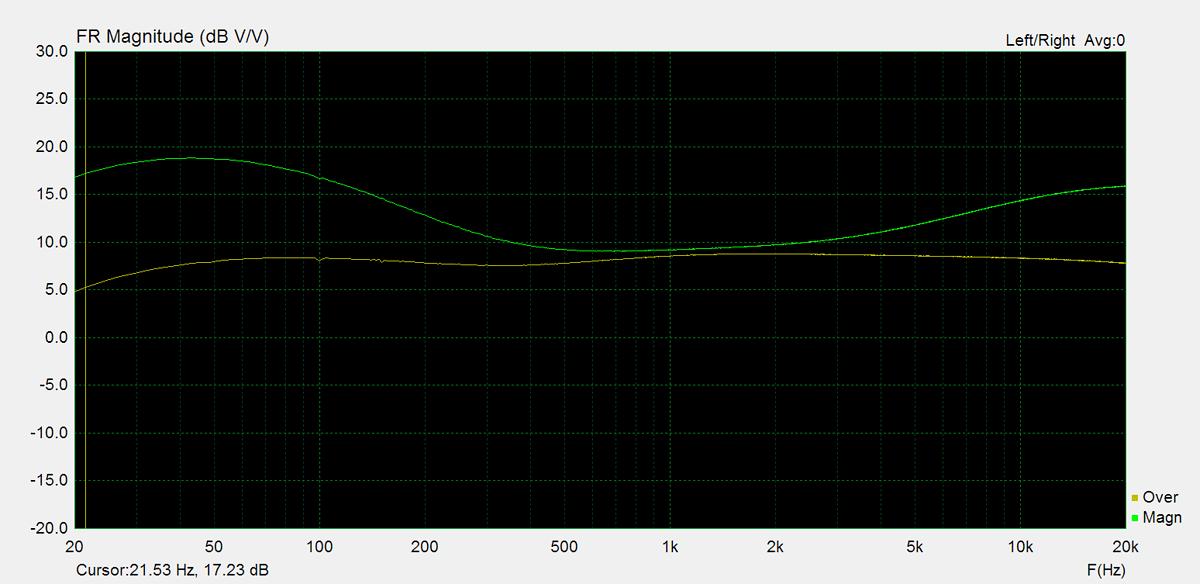
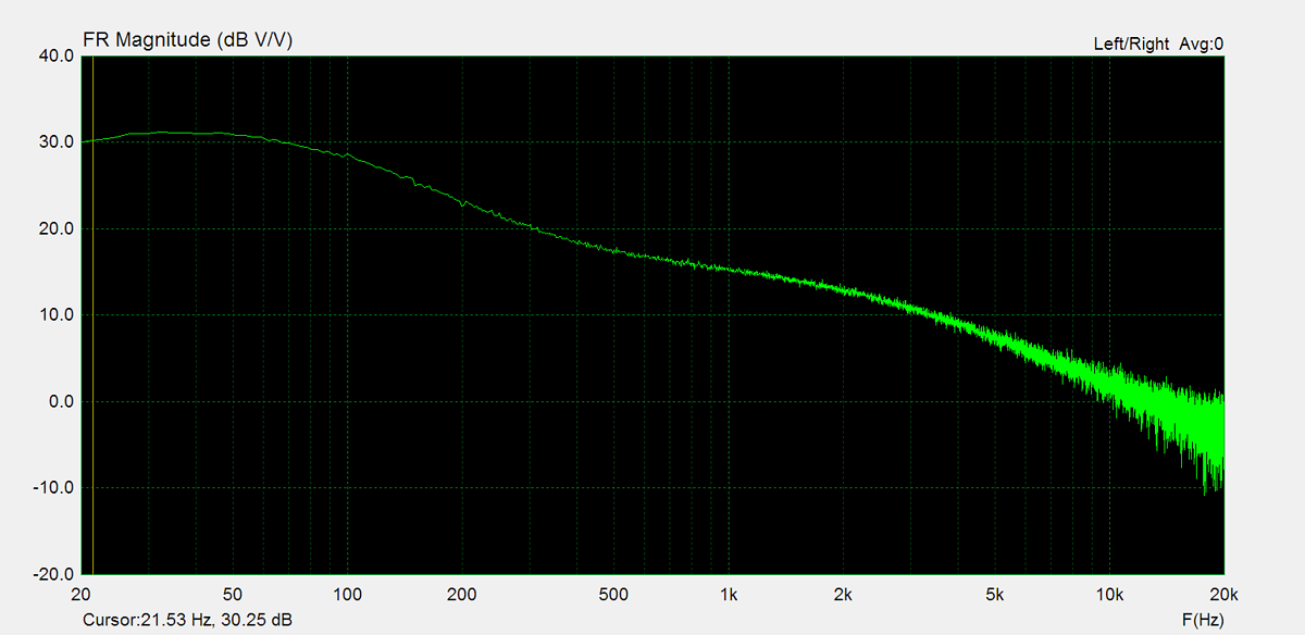
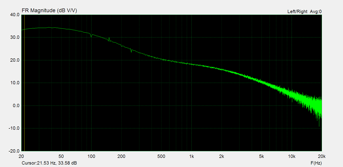
Frequency Response
Frequency response is measured using several equilizer settings. 'Flat' indicates the tone controls are either turned off or set to their neutral position. 'Max' and 'Min' refer to the maximum and minimum tone control positions, respectively. In the phono section, the expected response follows the RIAA equalization curve.
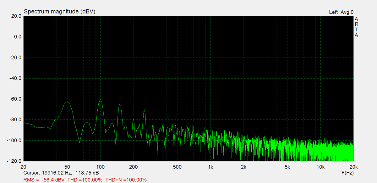
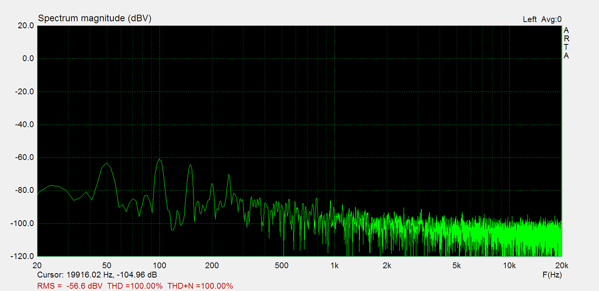
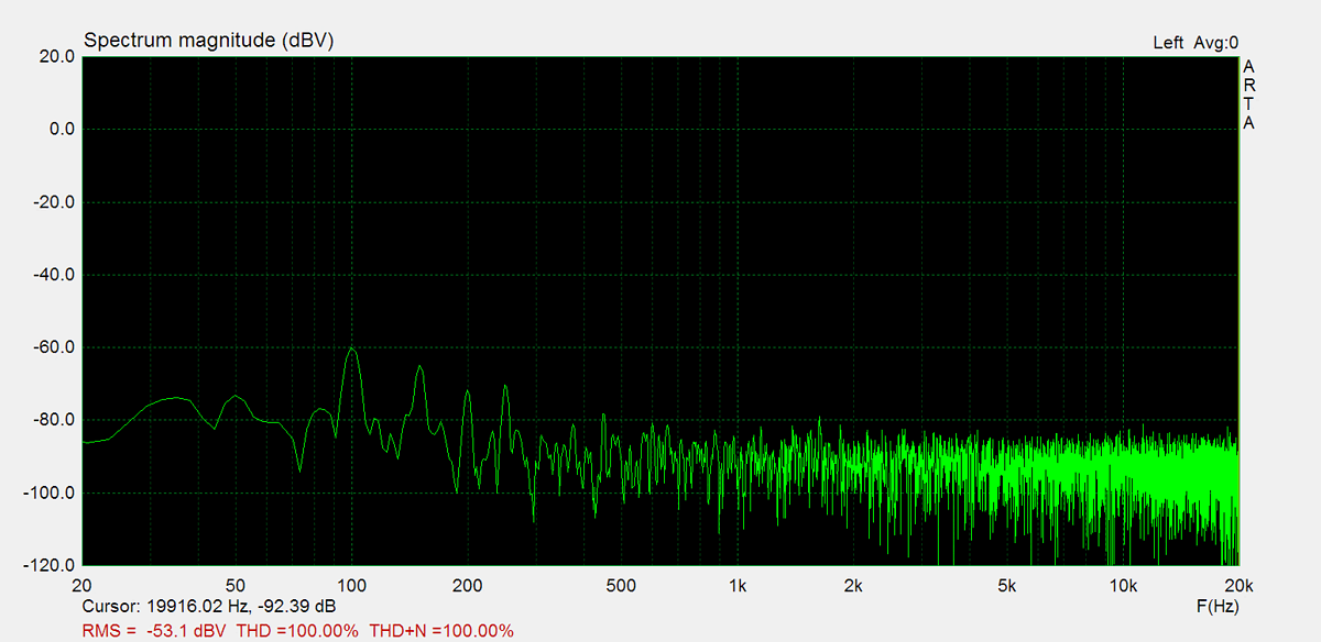
Residual Noise
These graphs display the noise levels at various volume positions. To eliminate any interference from the input signal, the input lines are shorted during the measurement. Generally, the noise is highest at the mid-point of the volume range (50%)
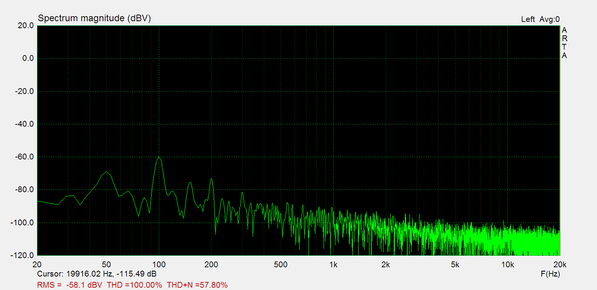


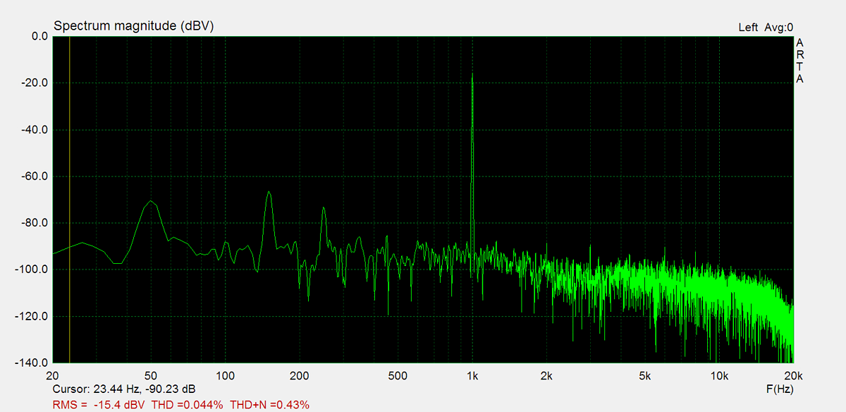
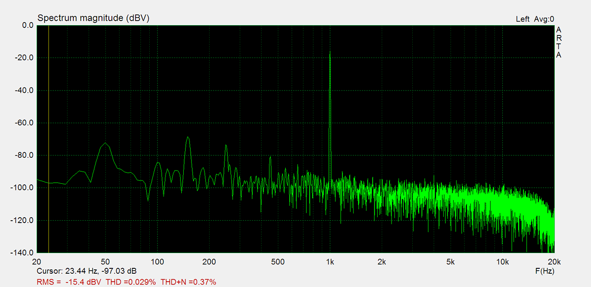
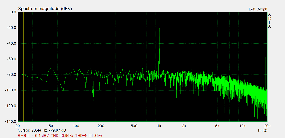
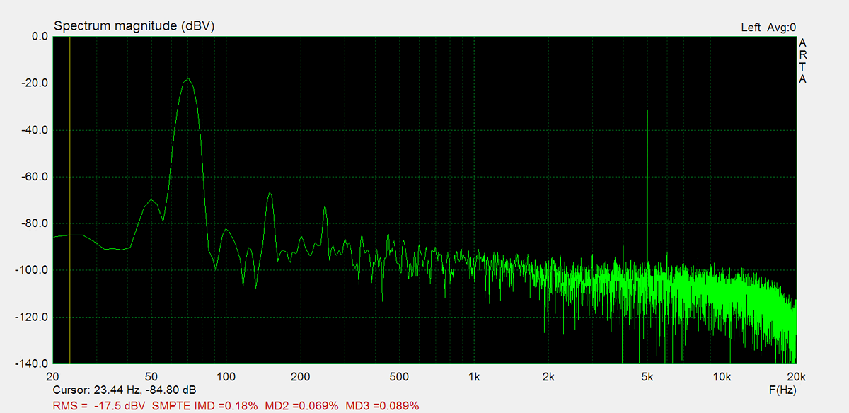
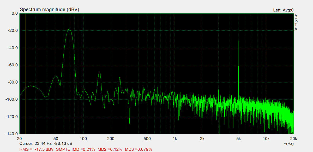
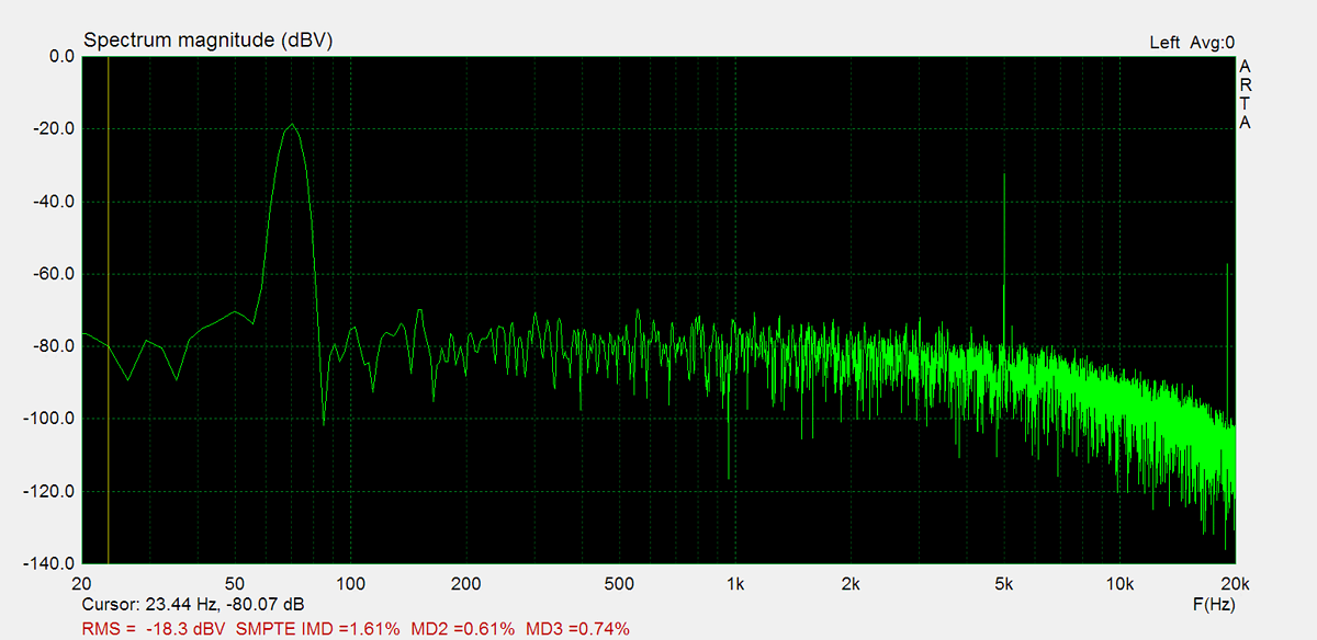
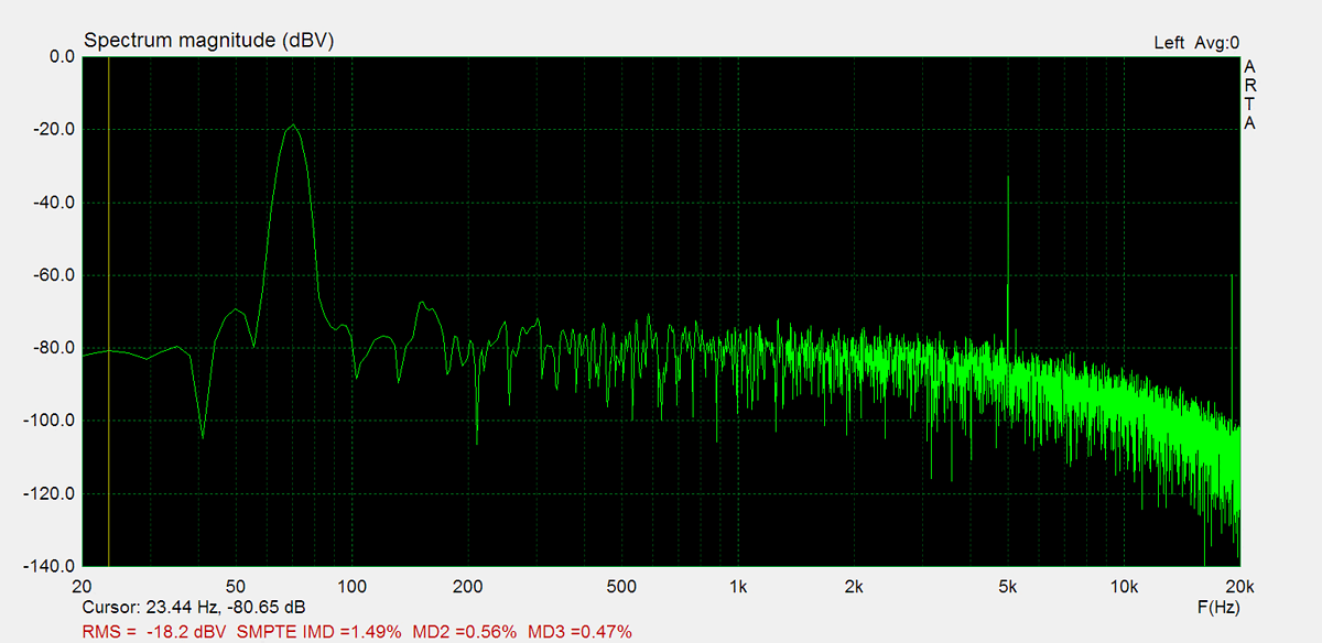
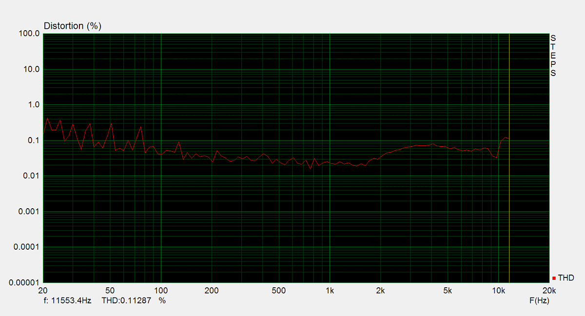
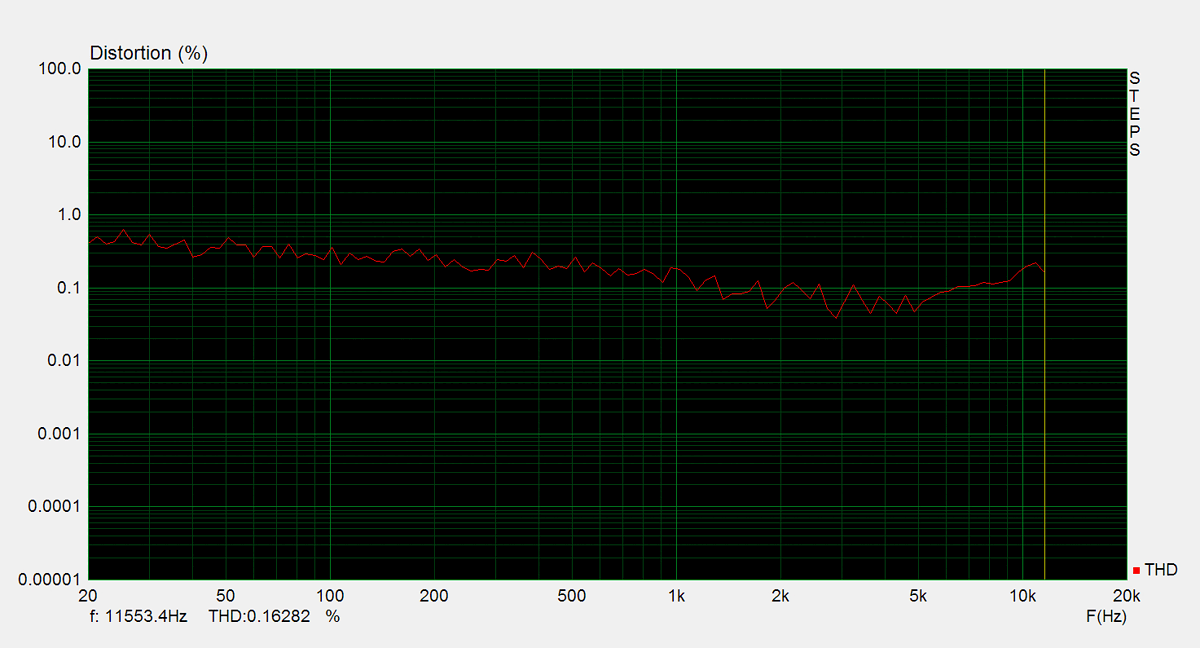
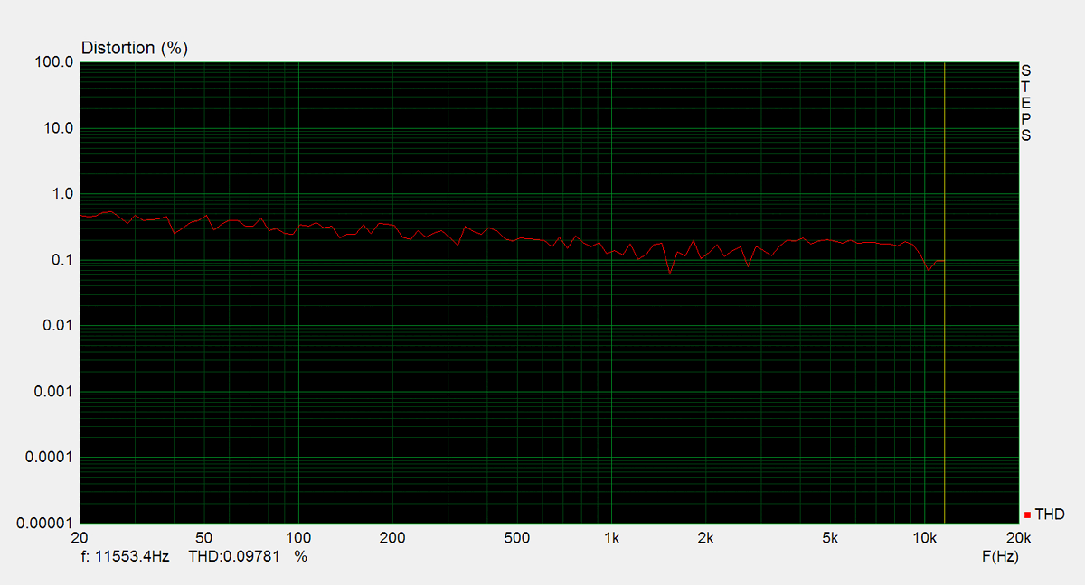
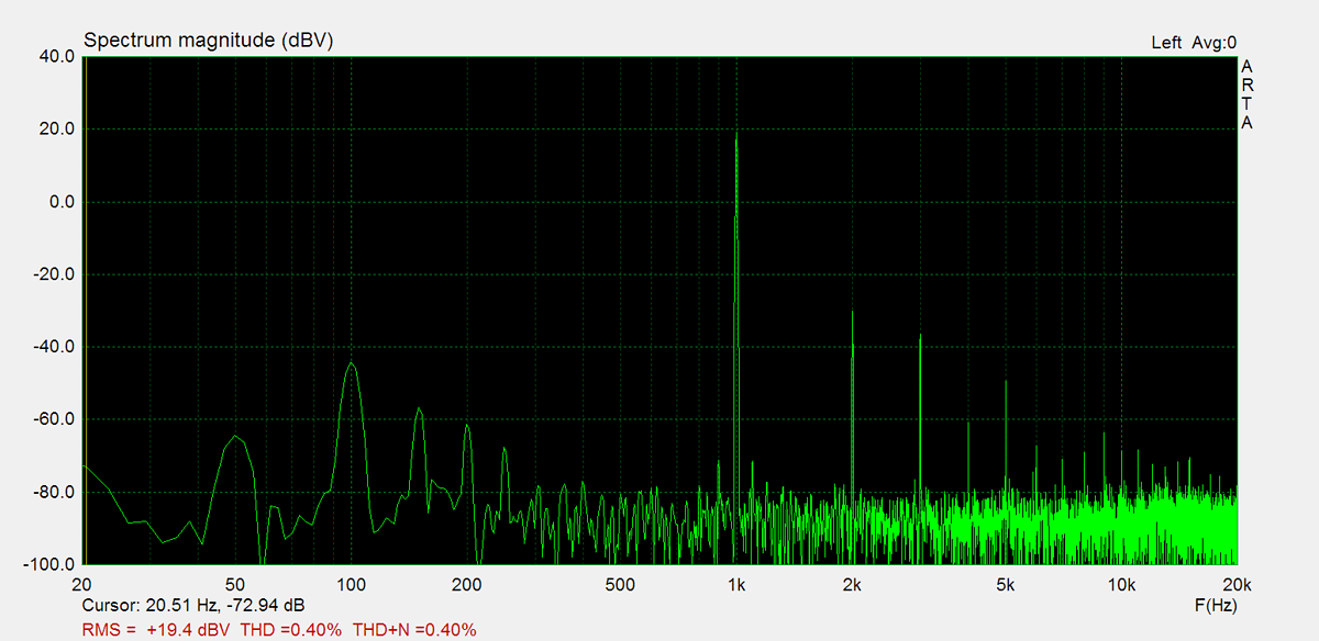
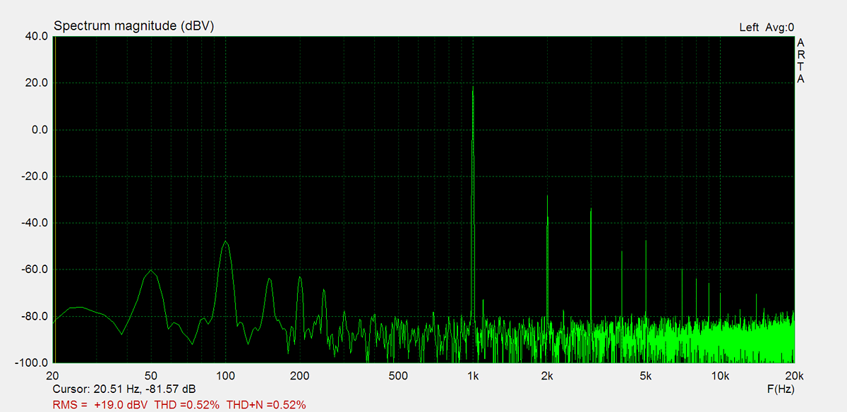
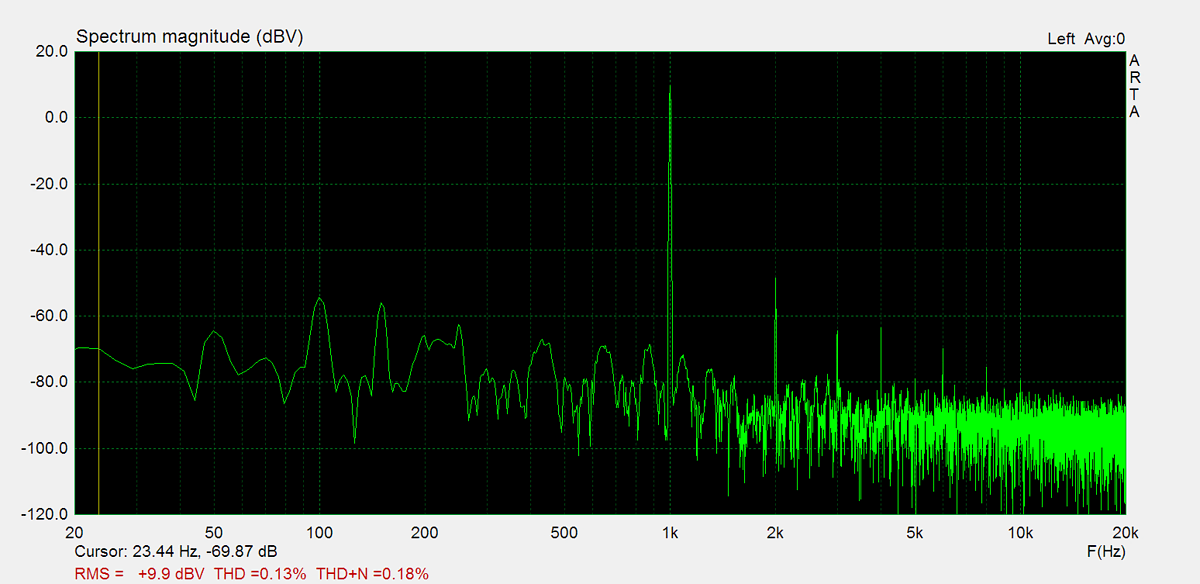
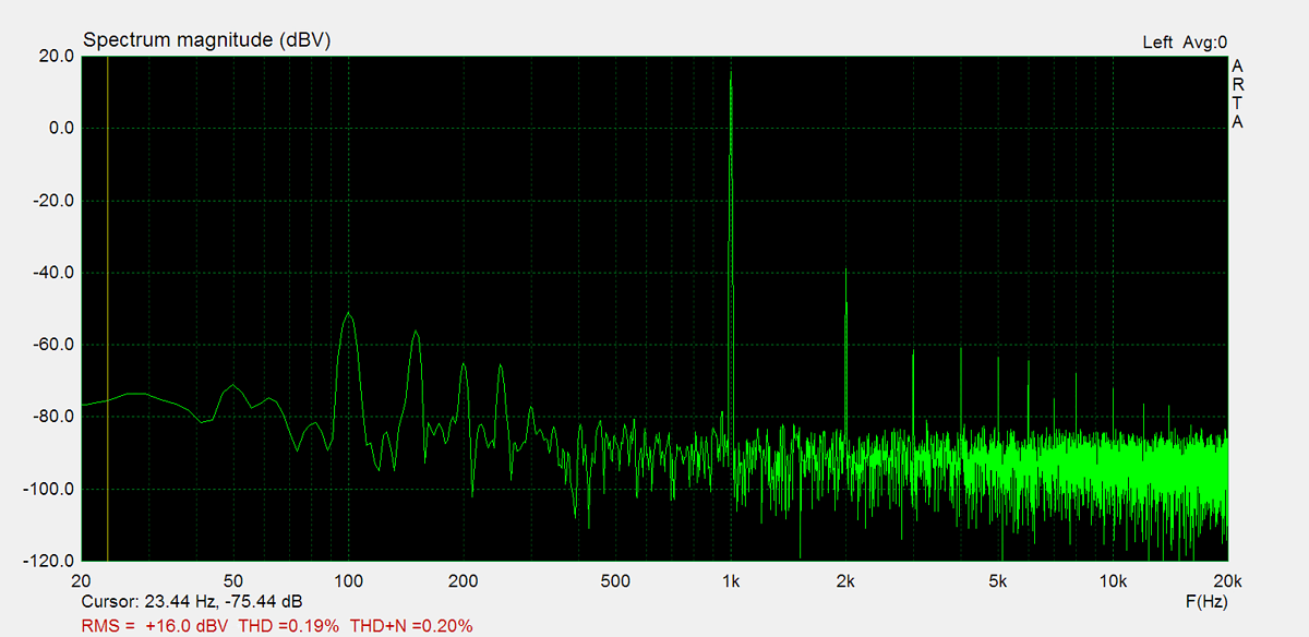
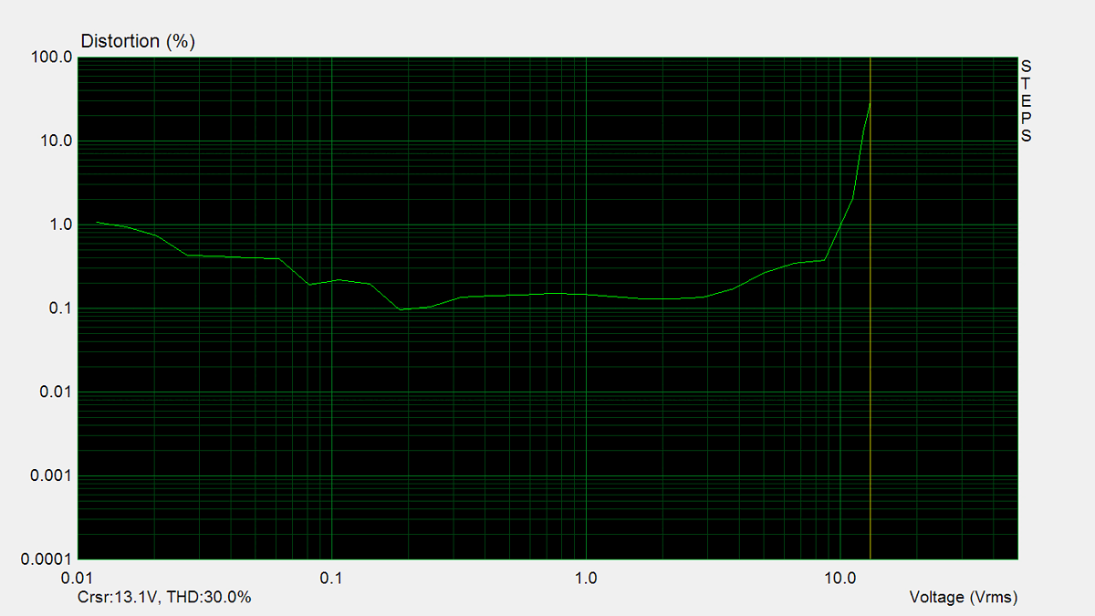
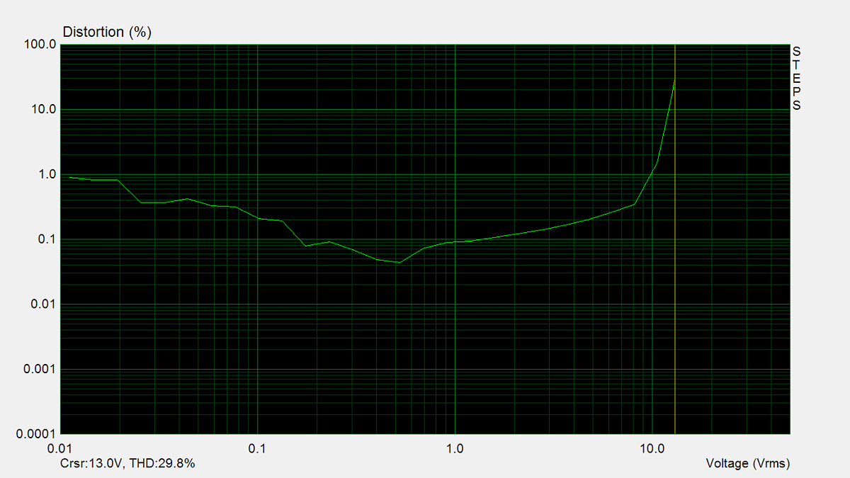
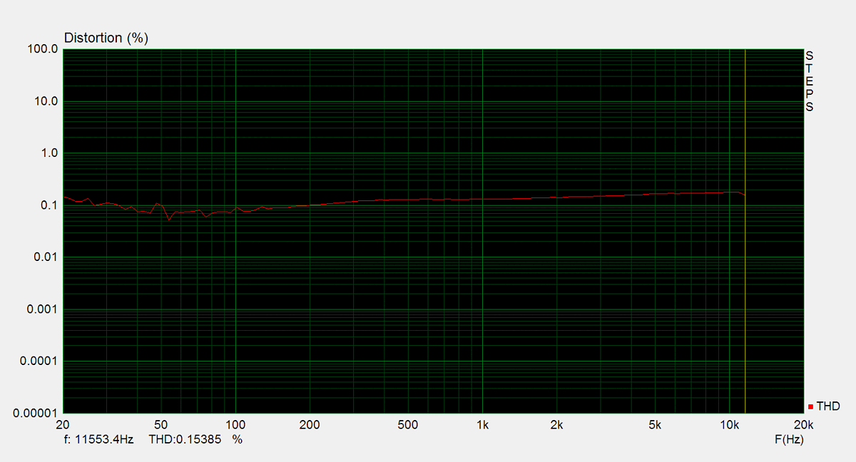
Distorsion
Total harmonic distortion (THD) is measured using a 1kHz sine wave input, with the output level adjusted to meet different conditions. Intermodulation distortion (IMD) is measured using 'two sine' input signal. THD versus voltage is measured with a 1kHz sine wave input, while THD versus frequency is measured at various output levels.


FM Tuner
Measurements of the tuner section were performed using an FM signal generator, with its output fed directly into the antenna input. AM measurements were not conducted.