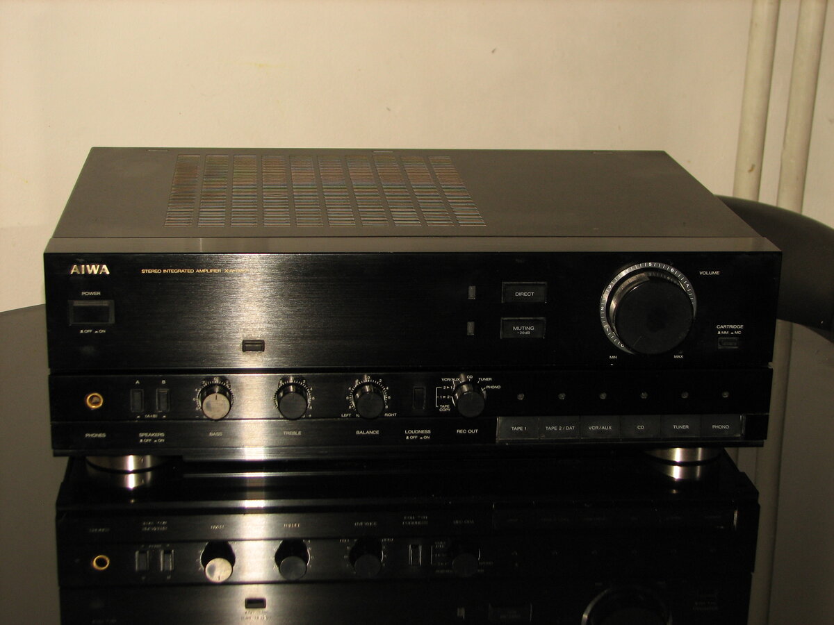
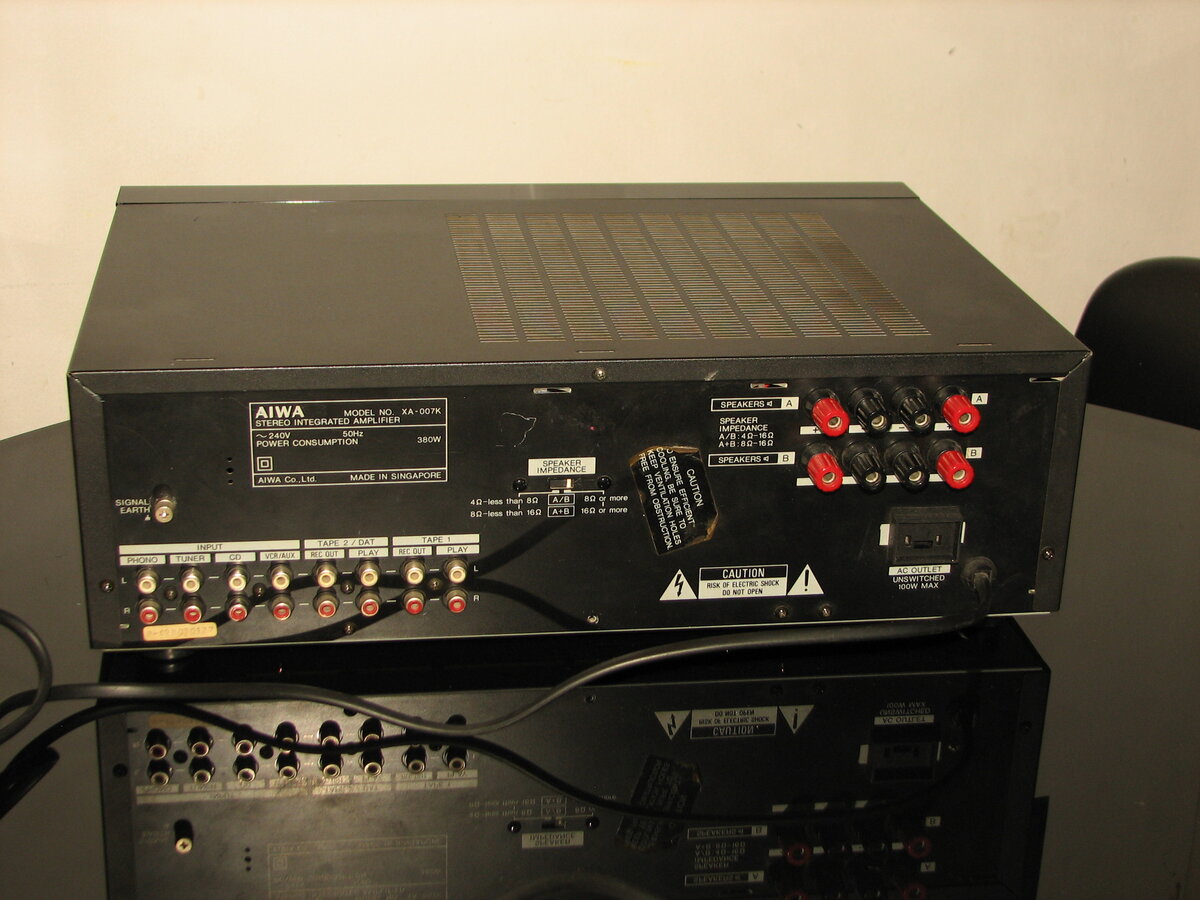
Aiwa XA-007
The Aiwa XA-007 is a stereo integrated amplifier produced in the early 1990s, known for its good performance and versatile connectivity options. With solid build quality and support for both MM and MC phono cartridges, it remains a dependable choice for audio enthusiasts seeking vintage gear with high fidelity and flexibility.
General Specifications
Maximum power (8Ω): 80WFrequency response (5Hz-100kHz): 0,-3dB
Frequency response (20Hz-20kHz): <0.05%
THD (80W, 4-8Ω): 0.9%
THD (65W, 8Ω): 0.007%
Signal to noise ratio (Line): 105dB
Signal to noise ratio (MM): 94dB
Signal to noise ratio (MC): 75dB
Speaker load impedance: 4Ω-16Ω
Dimensions (WHD): 430×140×335mm
Weight: 8.4kg
Produced: 1989-1992
Initial price: 700DM
Measured Values
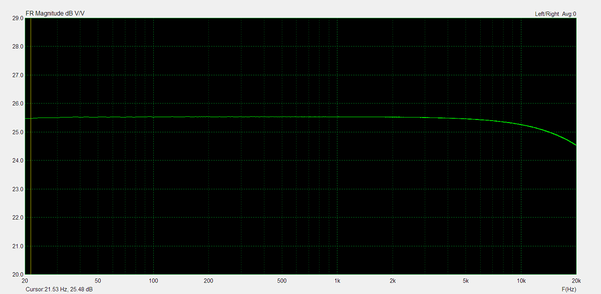
Maximum power (8Ω): 80WFrequency response (20Hz-20kHz): <1dB
Channel imbalance: <1dB
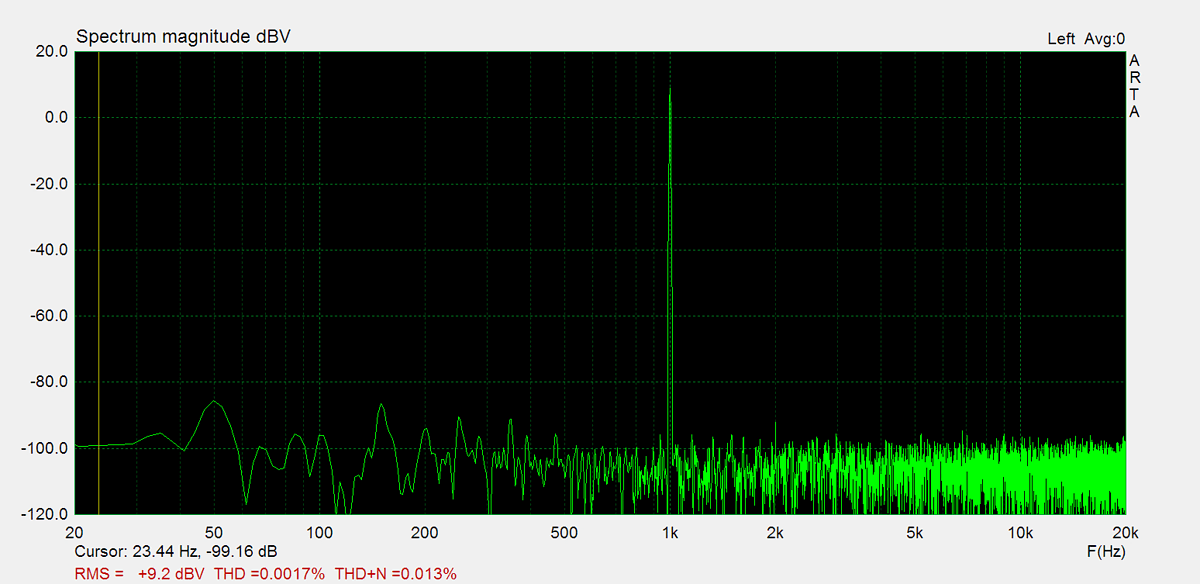
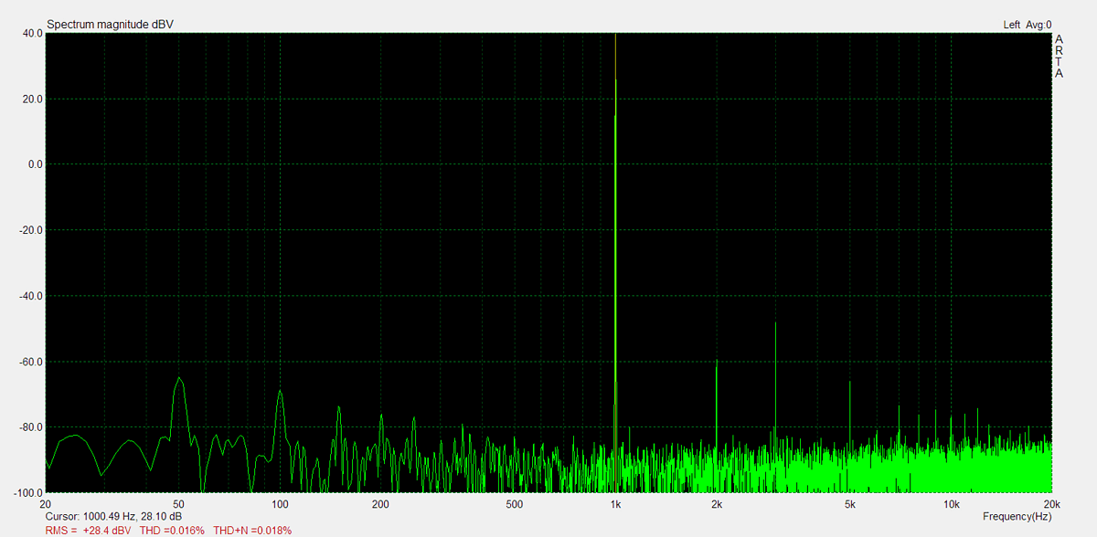
THD (1kHz, 1W): 0.0017%
THD+N (1kHz, 1W): 0.019%
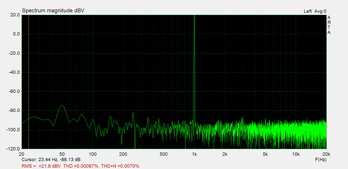
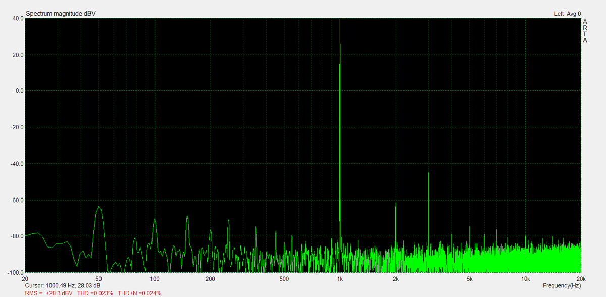
THD (1kHz, 20W): 0.015%
THD+N (1kHz, 20W): 0.024%
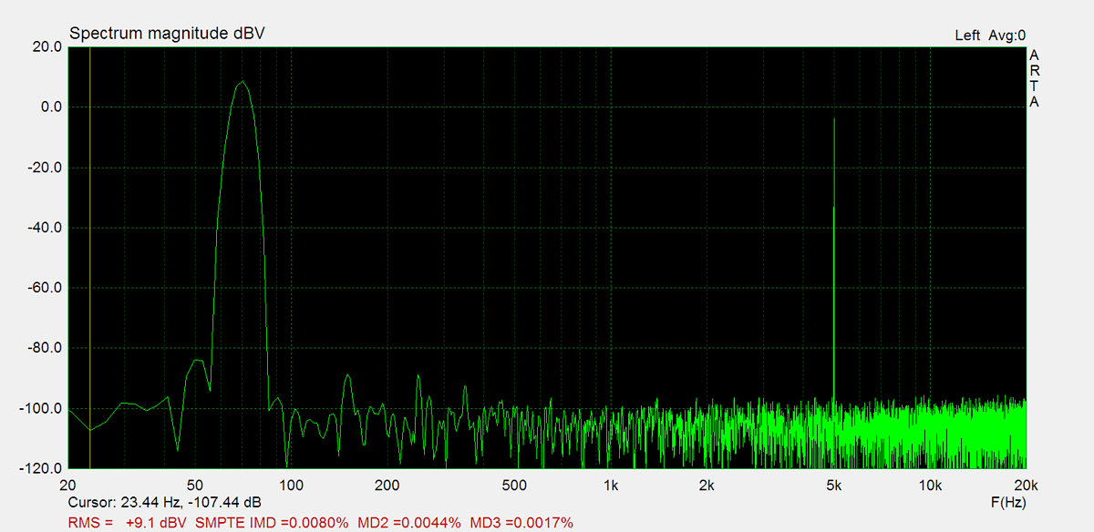
IMD (70Hz, 5kHz, 1W): 0.0065%
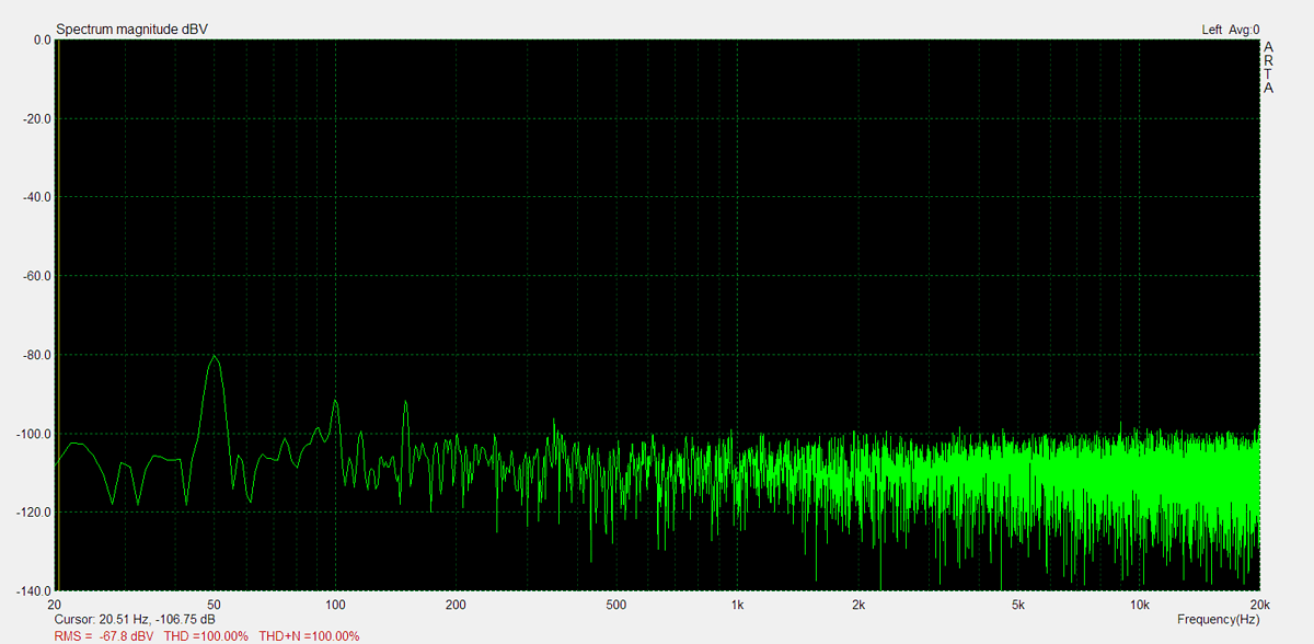
Noise: -67.8dB
Amplification (Line): 172.8
DC offset L: 1.5mV
DC offset R: 3.3mV
Maximum Power
Maximum power is measured using 8Ω resistors on both channels. A 1kHz sine wave input signal is applied and gradually increased until higher harmonics rise significantly. Typically, this is the point at which output clipping occurs.
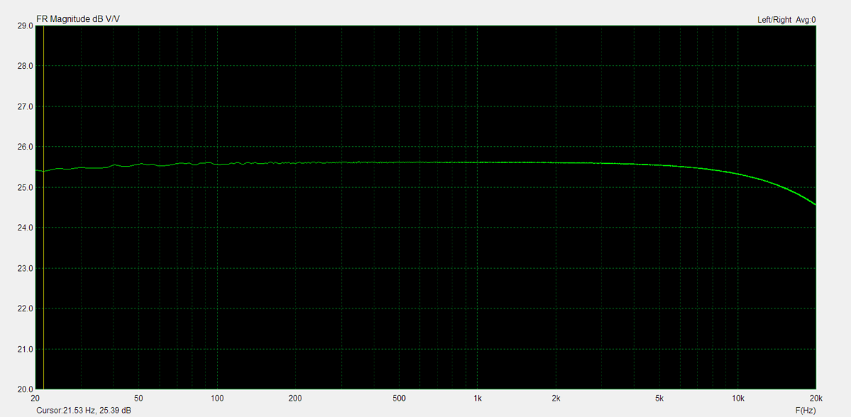
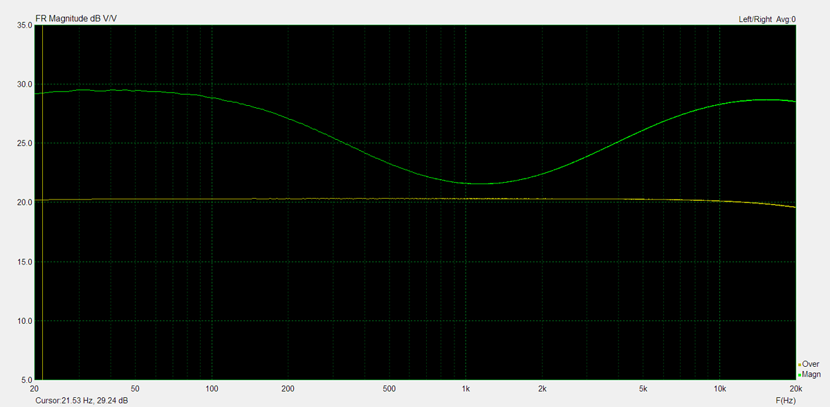
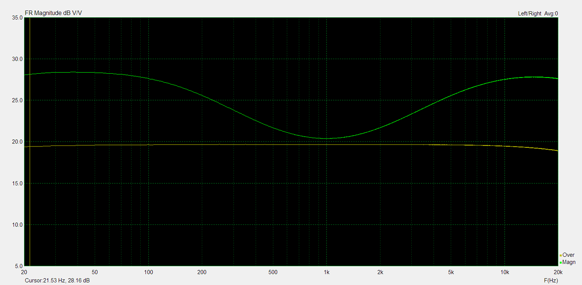
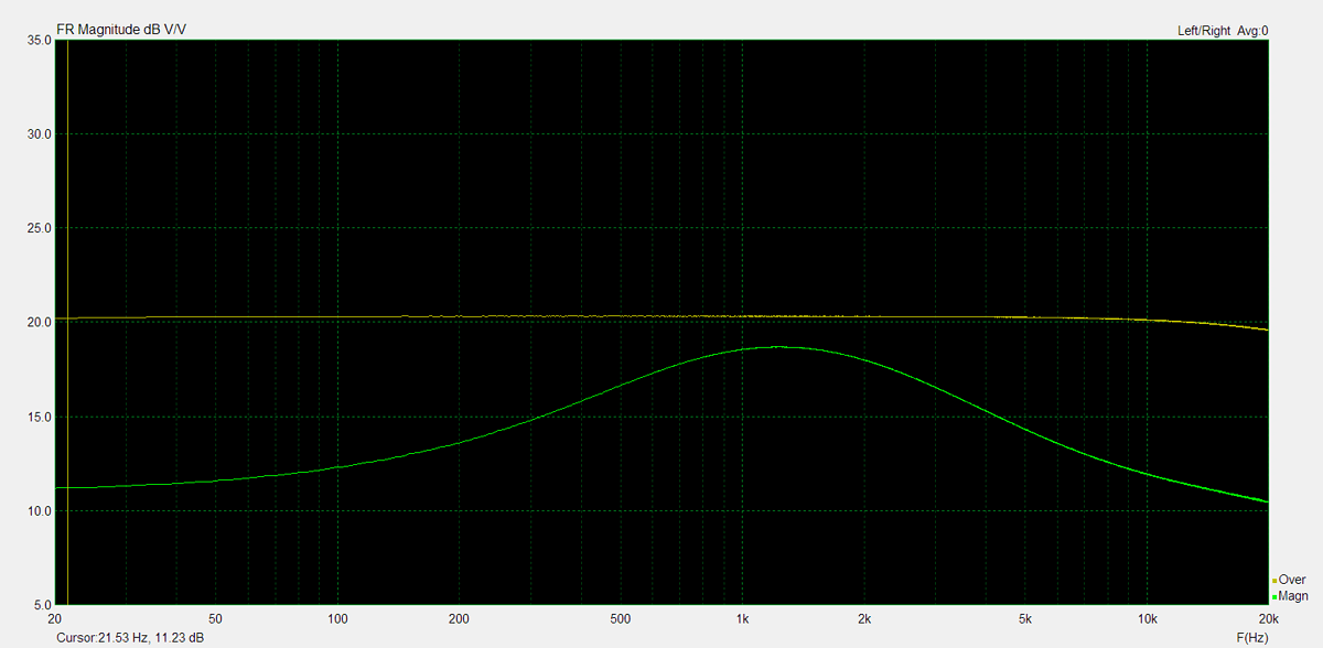
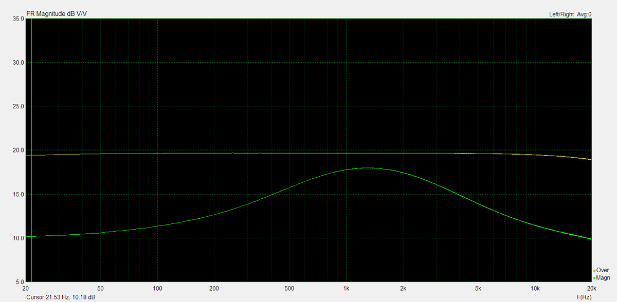
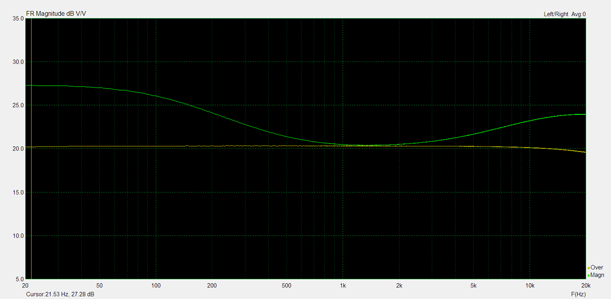
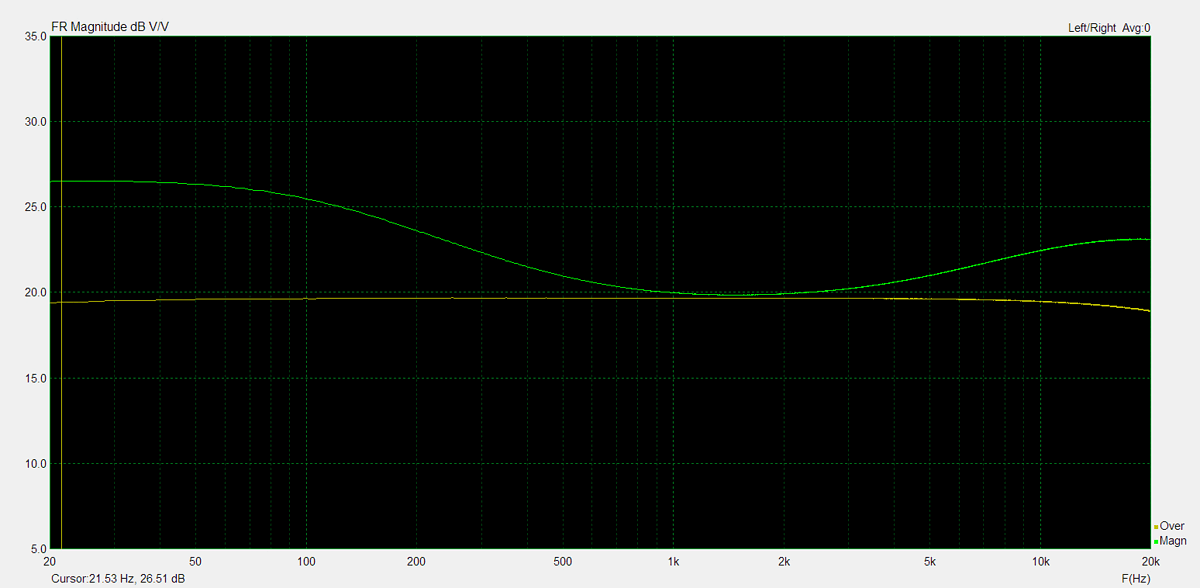
Frequency Response
Frequency response is measured using several equilizer settings. 'Flat' indicates the tone controls are either turned off or set to their neutral position. 'Max' and 'Min' refer to the maximum and minimum tone control positions, respectively. In the phono section, the expected response follows the RIAA equalization curve.
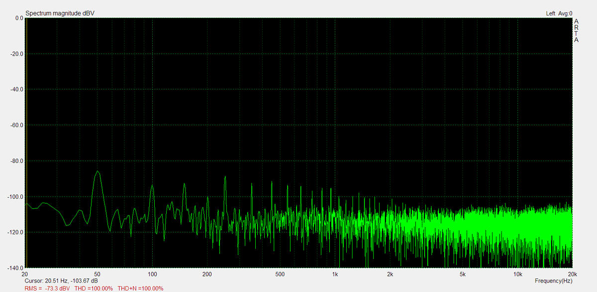
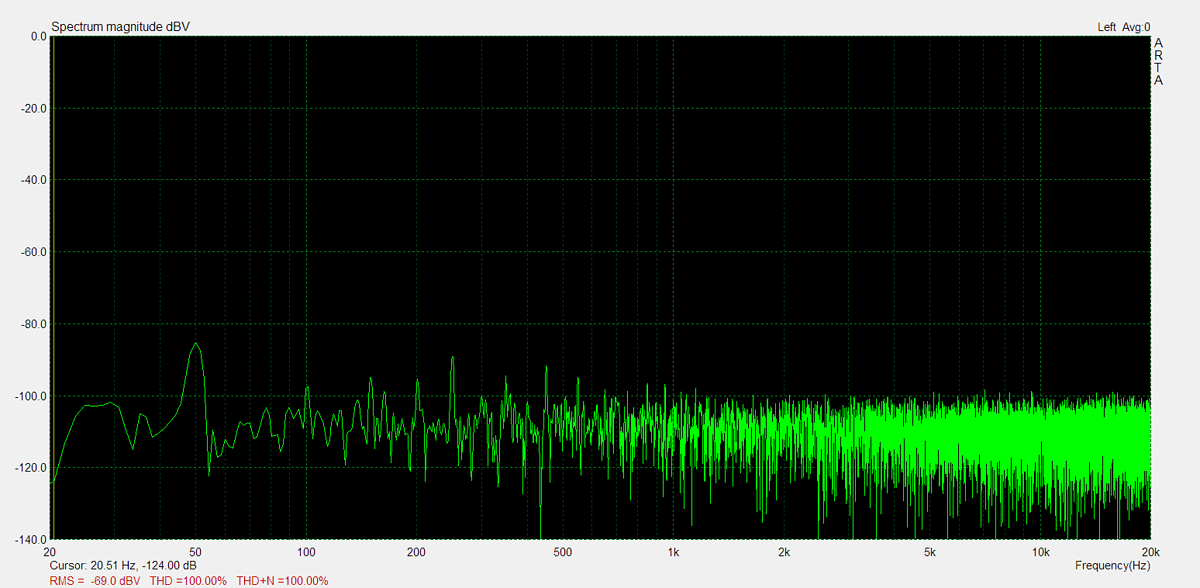
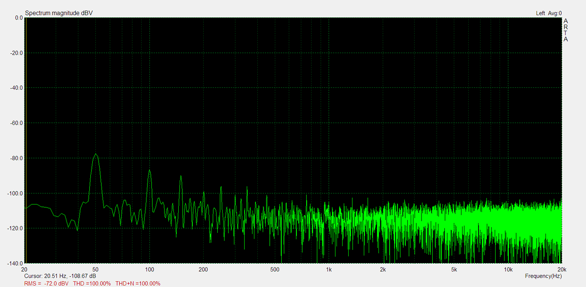
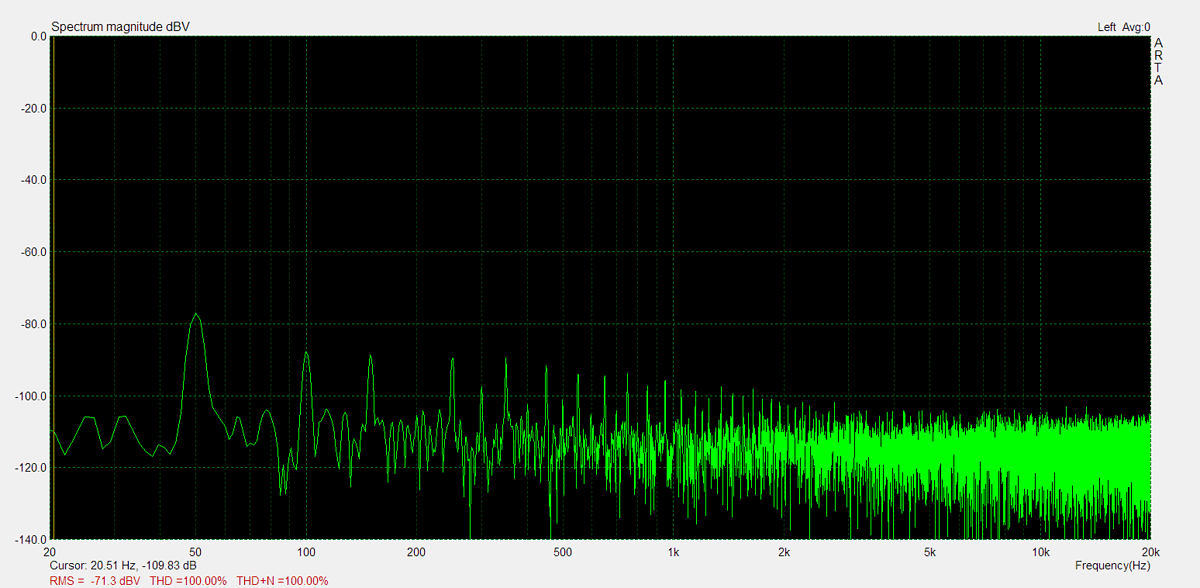
Residual Noise
These graphs display the noise levels at various volume positions. To eliminate any interference from the input signal, the input lines are shorted during the measurement. Generally, the noise is highest at the mid-point of the volume range (50%)

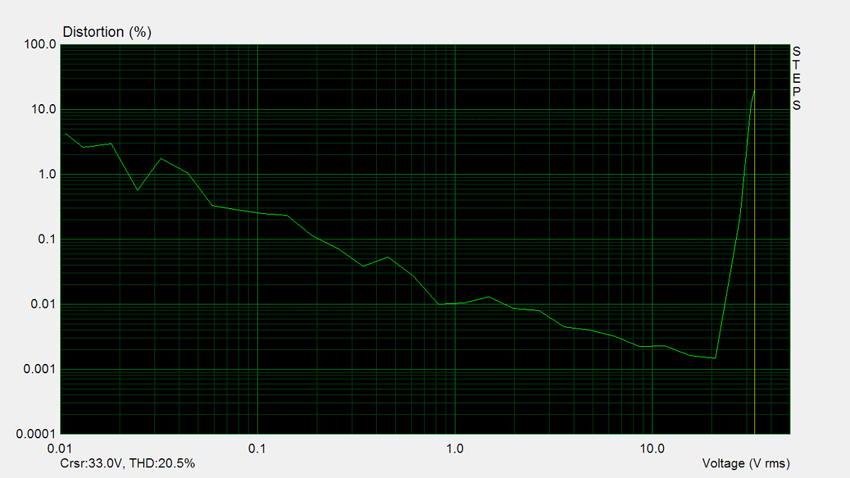
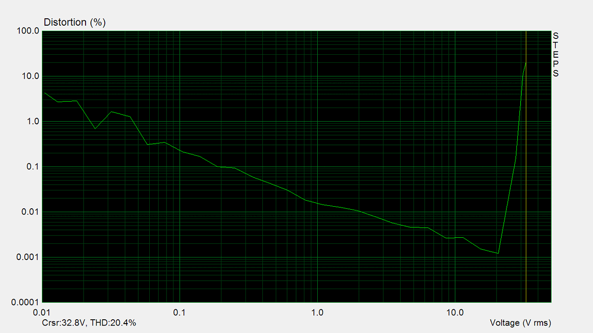
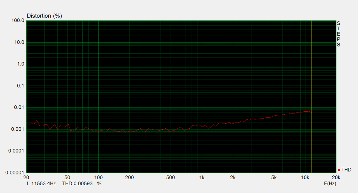
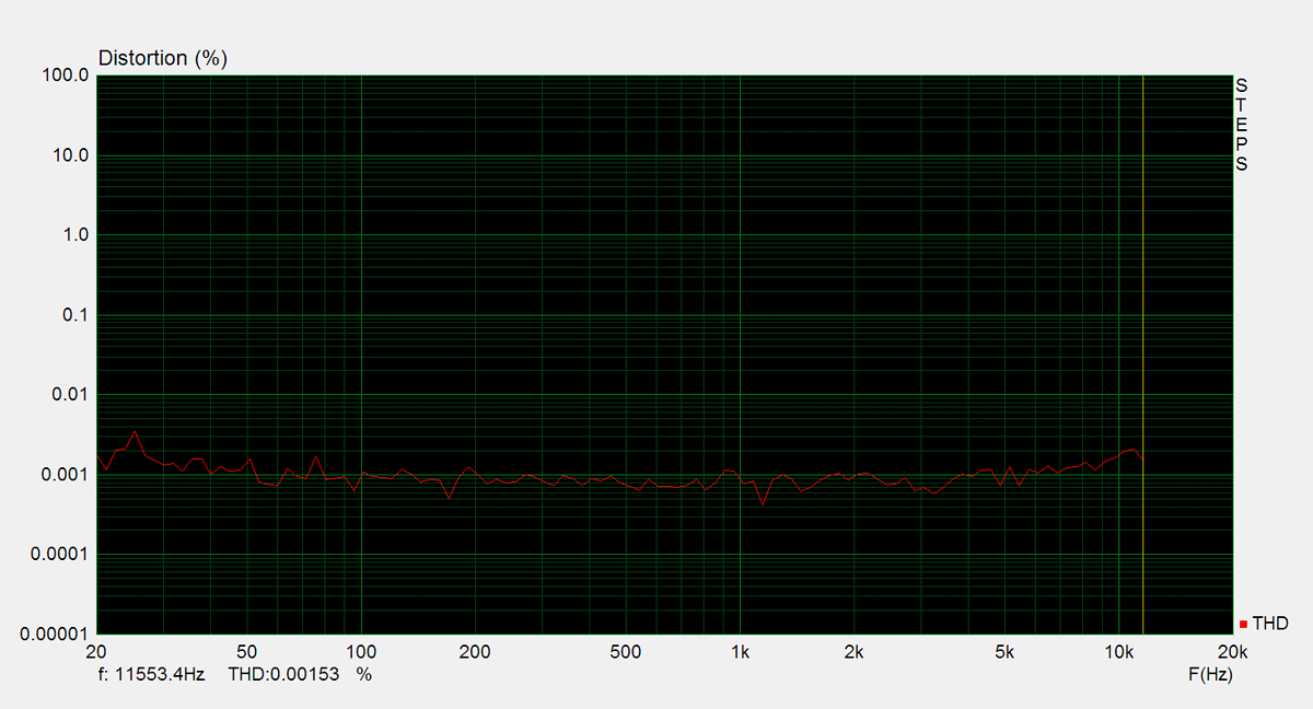
Distorsion
Total harmonic distortion (THD) is measured using a 1kHz sine wave input, with the output level adjusted to meet different conditions. Intermodulation distortion (IMD) is measured using 'two sine' input signal. THD versus voltage is measured with a 1kHz sine wave input, while THD versus frequency is measured at various output levels.